Maintenance
|
Maintenance |
|
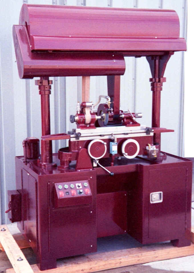
Model 1018 Uni. on 90" cabinet
|
Your Crystal Lake Cylindrical Grinder should be maintained like a fine tuned instrument. Keeping it in top condition requires a few simple steps to assure trouble free performance and years of service.
(1) Remove dust cap (on Wheelhead only) (2) Loosen set screws on spindle nut (3) Turn to Right until end play (using dial indicator) is less than .0002" High Speed Steel Spindles run from .0002" to .00002". All adjustments should be made after bearings have been run and are warm. Lubricant should be a light to medium hydraulic oil. 10, 20 S.A.E or DTE 24 Hydraulic oil. Spindles run on the hydroplaning principle. The spindle needs to float on a thin film of oil. Therefore excessive belt tension or over tightening end play constantly will only cause premature ware. Allow bearings after adjustment to find where it wants to run and leave it to hydroplane. The thicker the oil the more gap will be required. [Top]
(1) Loosen In-Feed Hand Wheel set screws (2) loosening rear set screw above eccentric housing (3) rotating eccentric housing to set gap between worm and worm-gear (4) Tighten set screws again If Platen is removed for any reason, care must be taken when re-engaging the rack as the rack can easily get caught on top of pinion teeth and cause breakage of pinion and/or rack. [Top] Proper tension is essential on the Wheelhead Endless Belt for prevention of Spindle binding and Belt slippage. Excess Belt tension forces the Spindle into the Bronze Bearing thereby eliminating the oil film space between the Spindle and Bearing surface for the Spindle to glide on. Of Course, Belt slippage is caused by a lack of tension. Steps to take for proper tension: 1) Align Swivel Table. 2) Level Table with a level. 3) Set Wheel 1/2" from Tailstock Dust Cap. 4) Drop Countershaft by backing off the Upright Adjusting Rings until the Belt is loose. 5) Level the Countershaft by placing a level on the steel or aluminum Workhead Belt Driving Drum and adjusting the Rings until the Belt Driving Drum is level. 6) Once the Belt Driving Drum is level, start adjusting each Ring evenly 1/2 turn at a time. 7) When Belt starts to snug up start the Wheelhead Motor. If Belt slips then shut off Motor; tighten Belt by adjusting Rings evenly 1/2 turn at a time. 8) You may have to start and stop Wheelhead Motor and make the 1/2 turn evenly with the Adjusting Rings several more times. 9) When Belt grabs, Adjust each Ring 1/2 turn past that point. 10) Belt should look as if it is loose and slapping. You have a proper Belt tension as long as the Spindle turns without sticking and Belt is not slipping. CAUTION Too much tension on the Wheelhead Flat Endless Belt causes the Spindle to stick or bind and creates excessive wear on Bearings. [Top] |
Send mail to clg@netptc.net with
questions or comments about this web site.
|