Wiring Diagrams
|
Wiring Diagrams |
|
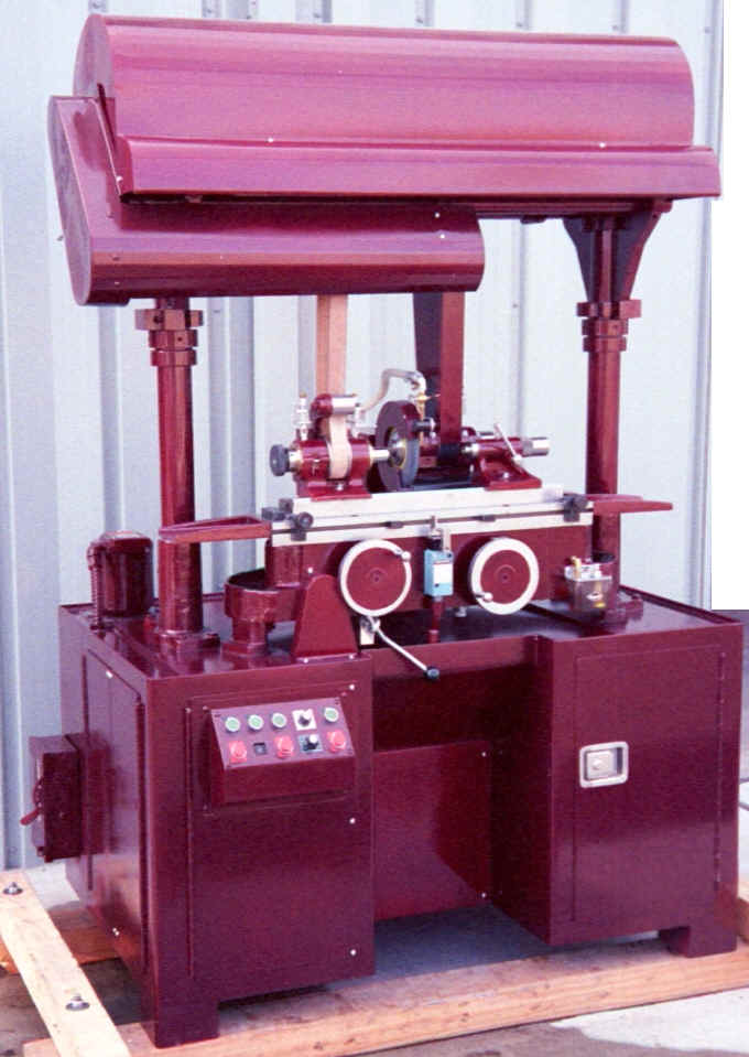
Model 1018 Uni. on 90" cabinet
|
Workhead D.C. Wiring Instructions
(1) Remove existing electric components for Workhead from grinder cabinet. Leave the five (5) wires that run through the countershaft upright tube to the Motor. (Label as listed on old controller.) You can use old push-buttons, the Allen Bradley Contactor. (9 contacts - use 2.) Fuses etc. (2) Mount Potentiometer on push-button control panel near Workhead Switches. (3) Mount new DC Electric Board in elec. cabinet close to upright tube. (4) Mount two (2) fuse block, with fuses. (or use existing fuse blocks). (5) Connect A1 and A2 lines from motor, to the new DC Electric Board. (Switching A1 and A2 reverses motor rotation) (6) Connect (F1, F2) or (+F, -F) lines from motor, to the new DC Board. (7) Connect Shielded Three Wire Cable from the New Board to the Pot. (Shielded cable Purchase locally) (a) Connect S2 from DC board to the center Potentiometer connection. (b) Connect S1 and S3 from DC Board To the Potentiometer. (solder). (Switching S1 and S3 at board if Speed Control needs to be reversed) If motor runs noisy use choke from old control. The High Grade DC Controller reduces noise. [Top]
|
Send mail to clg@netptc.net with
questions or comments about this web site.
|